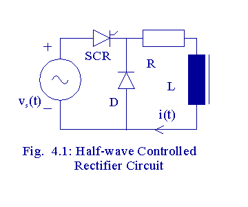
The operation of a half-wave controlled rectifier circuit with a free- wheeling diode is illustrated in this program. Let vs(t) be defined to E * sin (wt). During 0 < wt < a, the current through the circuit would be zero without a free-wheeling diode. When there is a free-wheeling diode, there is current through the load, maintained by the inductor discharging its energy. With an SCR, the conduction starts when it is triggered at wt = a and the SCR continues to conduct till wt = p. When wt = p, the source becomes zero, but at this instant, the current through the circuit is not zero and there is some energy stored in the inductor. When vs becomes negative, the current through the circuit would not become zero suddenly because of the inductor. The inductor acts as a source and keeps the diode forward-biased till the SCR is triggered in the next cycle. Then
L (di/dt) + Ri = E * sin (wt ) for a < wt < p,
L (di/dt) + Ri = E, for 0 < wt < a. and for p < wt < 2p .
The complementary solution is:
i(wt) = A *exp [- (R(wt - a) / wL ) ], where A is a constant to be evaluated.
The particular solution is:
i(wt) = [E/Z] sin (wt - f ), where f = tan -1 (wL/R) , Z 2 = R2 + (wL)2 .
The total solution is then:
i(wt) = [E/Z] sin (wt - f ) + A *exp [- (R/wL *(wt - a) ].
Since i(a) = i(p)* exp[-{R(p+a)/wL} ] , A can be obtained.
First specify the values of parameters as shown below.
E :=340 V R:= 10 W wL := 10 W f := atan(wL/R) f = 0.785 rad
Z := sqrt [(R2 + (wL)2)] Z = 141.42 W
Let firing angle a be: a := p/6 rad
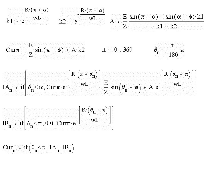
Define two constants, k1 and k2, to facilitate evaluation of the coefficient present in the total solution of current. The current flowing through the load at wt = p is evaluated next. It is called Curp. A range varibale, n corresponding to number of degrees in a cycle is defined next.
Then compute qn in radians. It is an array of 361 elements.
Next compute an array of currents. This array calculates current using one expression if the angle is less than the firing angle and another if it is greater than the firing angle.
Next an array of currents is computed
for wt > p From the previous
two arrays, the array of currents corresponding to load
current is obtained.

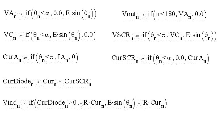
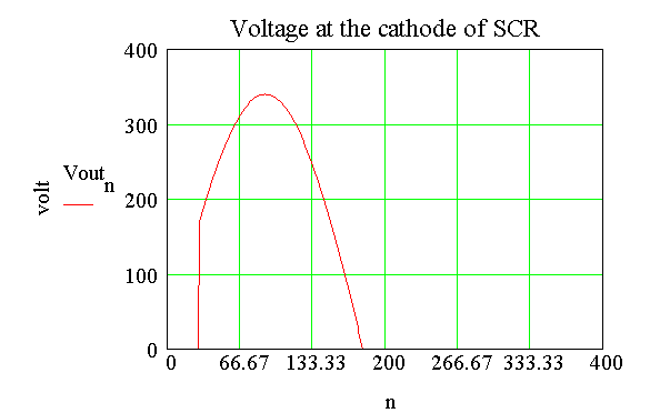
Next an array of voltages corresponding to the voltage at the cathode of the SCR, is obtained.
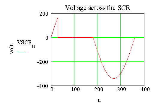
Next an array of voltages corresponding to the voltage across the SCR, is obtained.
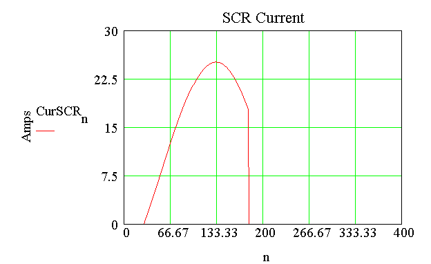
Next the current through the SCR,
is obtained.
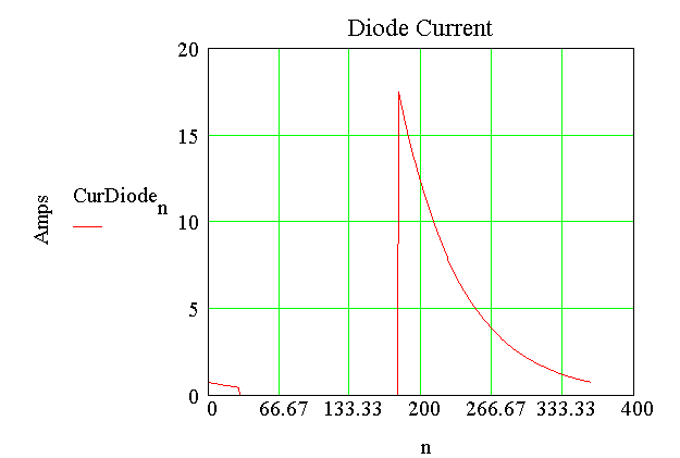
Then the current through the diode,
is obtained.
Next the voltage across the inductor
is obtained.
A = 6.67 Amp
Curp = 17.487 Amp
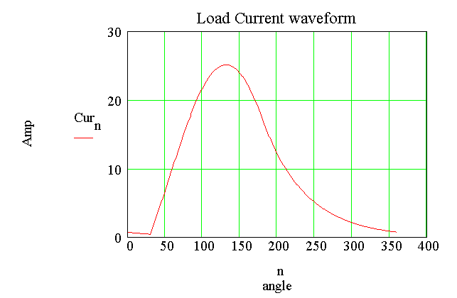
Next the average value of load current
is evaluated.
Next the rms value of load current
is evaluated.
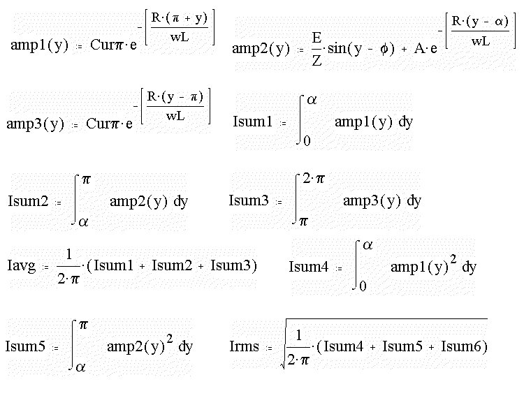
Iavg = 10.098 Amp
Irms = 13.334 Amp