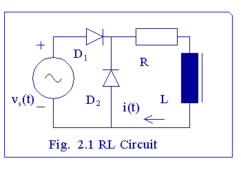

This circuit differs from the half-wave rectifier circuit without a free-wheeling diode. Without a free-wheeling diode, the current through the RL load is disontnuous, but it is continuous when there is a free-wheeling diode. Let vs(wt) = E*sin (wt). When 0 < wt < p, diode D1 conducts. When wt crosses p, vs becomes negative for p < wt < 2p. During this period, the inductor does not discharge its energy back to the source, for there is a path with a lower potential drop through D2. When p < wt < 2p, the current through the load decays exponentially. When the current response becomes periodic, the current at wt = 0 has the same value. Let the current at wt = 0 be A.
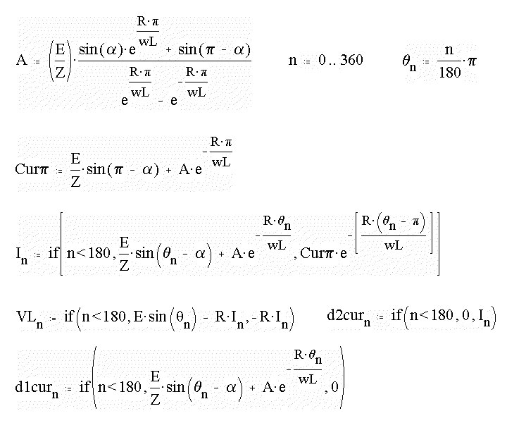
Then
A = i(p)*exp [- Rp / (wL)].
Also, i(wt) = [E/Z] sin (wt - a) + A *exp [- (Rwt)/(wL)], where a = atan (wL/R) and Z2 = R2 + (wL)2.
The value of A can be obtained from the above expressions.
E := 340 V
R := 10 W
wL := 10 W
Z := sqrt [(R2 + (wL)2]
Z = 14.142 W
a := atan(wL/R)
a
= 0.785 rad
Next the response over a cycle is computed. An array
is created. The array index corresponding to degrees is converted
to radians first. Next the value of load current at
wt = p is defined. Next an array called
In is created. In is calculated differently,
depending on whether the angle is less than or more than 180o.
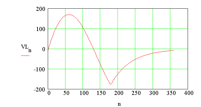
The voltage across the inductor is also stored as an array.
Again, it is calculated differently for angle less than 180o
or more. It is also
shown how the current through each of the diodes can
be computed.
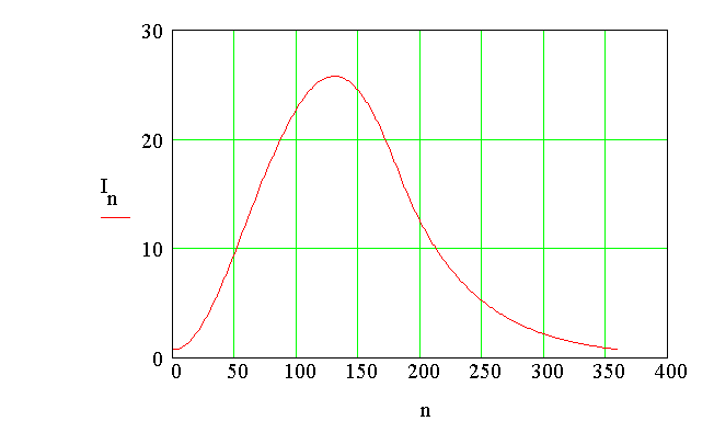
The plot of load current
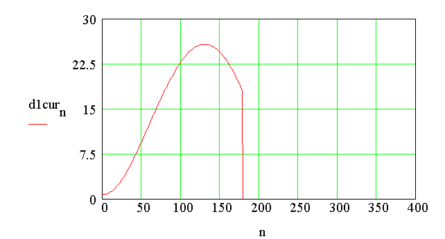
The plot of current through diode D1
The plot of current through diode D2
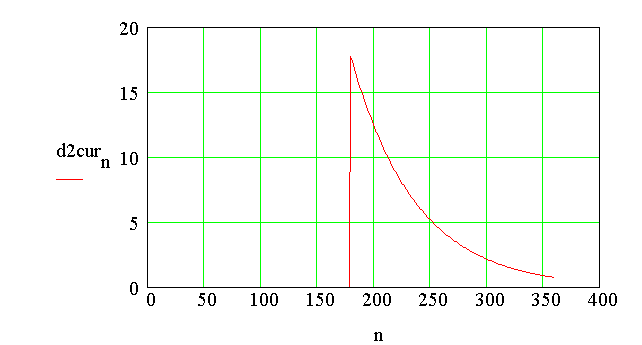
Plot of voltage across the inductor
Next the average and the RMS values of load current are computed. Two
functions are created, one corresponding to angle less than 180o and
the other corresponding to angle greater than 360o.
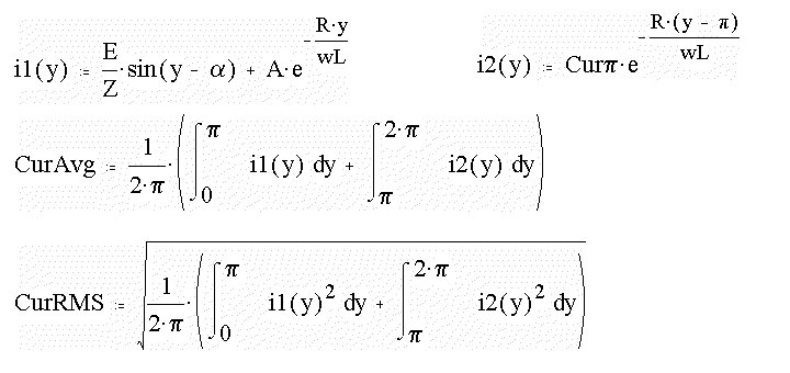
CurAvg = 10.823 Amp
CurRMS = 13.952 Amp