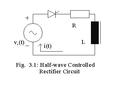

The operation of the RL circuit supplied by a half-wave controlled rectifier is illustrated in this program. Let vs(t) be defined to E * sin (wt). At wt = 0, the current through the circuit is zero. As wt becomes >0, vs becomes positive. If a diode instead of an SCR has been used, the diode would start conduction at wt = 0. With an SCR, the conduction does not start till the SCR is triggered. Let the SCR be triggered when wt = a. Then a is called the firing angle and the SCR continues to conduct.
When wt = p, the source becomes zero, but at this instant, the current through the circuit is not zero and there is some energy stored in the inductor. When vs becomes negative, the current through the circuit would not become zero suddenly because of the inductor. The inductor acts as a source and keeps the SCR forward-biased till the energy stored in the inductor becomes zero. Let the current through the circuit become zero at wt = b and the value of b > p. For b < wt < 2p, the current through the circuit is zero. Then
L (di/dt) + Ri = E * sin (wt ) for a < wt < b,
i(a) = i(b) = 0 , i(wt) = 0 for 0 < wt < a and
i(wt) = 0 for b < wt < 2p .
The complementary solution is;
i(wt) = A *exp [- (R(wt - a) / wL ) ], where A is a constant to be evaluated.
The particular solution is:
i(wt) = [E/Z] sin (wt - f ), where f = tan -1 (wL/R) , Z2 = R2 + (wL)2 .
The total solution is then:
i(wt) = [E/Z] sin (wt - f ) + A *exp [- (R/wL *(wt - a) ].
Since i(a) = 0 , A = [E/Z * sin (f - a)]. The solution is illustrated below.
First specify the values of parameters as shown below.
E :=340 V R:= 10 W wL := 10 W f := atan(wL/R) f = 0.785 rad
Z := sqrt [(R2 + (wL)2)] Z = 141.42 W
Let firing angle a be: a := p/6 rad
Next compute the coefficient
A as shown below. Then define a range variable n to find solution at each
degree within a cycle and express the angle within a cycle in radians.
Find the load current. If the angle is less than the firing angle, assign
it zero value The expression for load current calculated thus would be
negative if wt
exceeds the extinction
angle, b.
The extinction angle is that angle at which load current becomes zero.
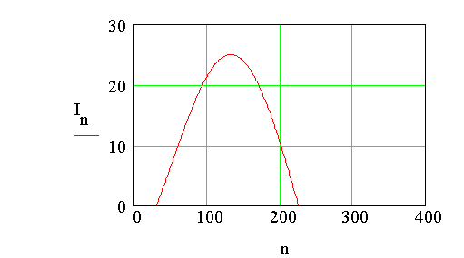
Create an array for current, called In. This array has the same
value as Curn if Curn >0.0. Otherwise the other
elements of array In are set to zero.
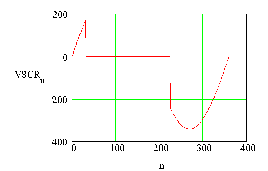
The voltage across the SCR is zero when In > 0. Otherwise it is equal to the applied voltage. Note that when wt < a , the voltage across the SCR is positve. Then the SCR blocks forward conduction. Next find the extinction angle. Assign a guess value first.
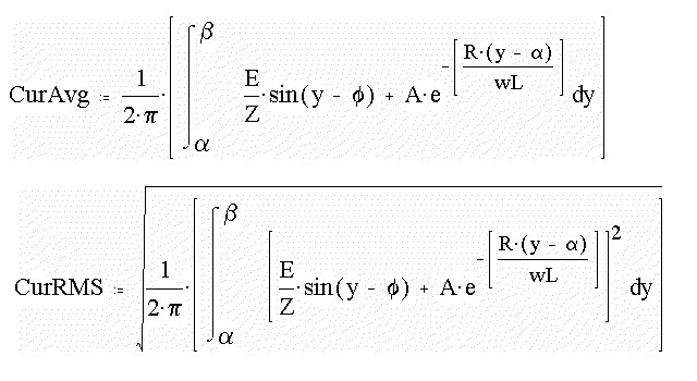
Next the average value of load current is found out. The RMS load current is evaluated after that.
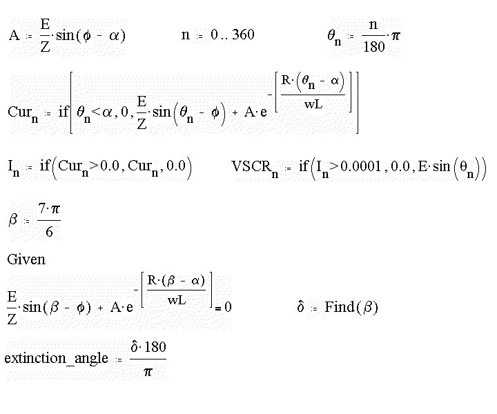
A = 6.222 Amp d = 3.936 rad
extinction_angle = 225.489 deg
The extinction angle is computed to be 225.49o.
Curavg = 8.339 Amp
CurRMS = 12.851 Amp
The load current waveform
The voltage across the SCR
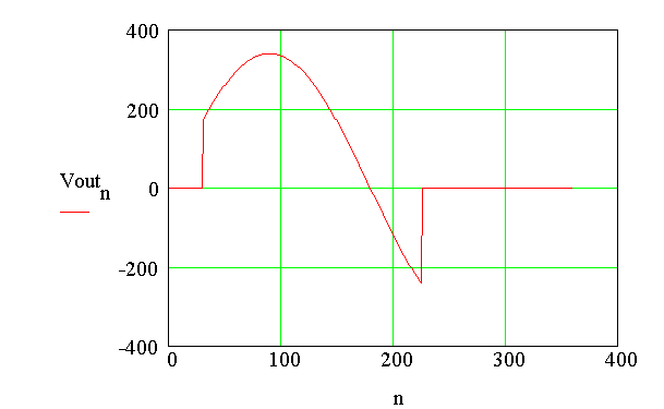
The Plot of Output Voltage
Voutn : = if (n > 0.001, E.Sin(qn),
0.0)
