THE
SINGLE-PHASE FULLY-CONTROLLED BRIDGE RECTIFIER
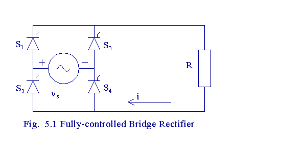
The operation of a fully-controlled
bridge rectifier circuit is explained in this program. The load is set
to be purely resistive. This bridge rectifier is called as fully-controlled,
because all the devices used are SCRs.
As the load is purely resistive,
the load current waveform follows the load bridge rectifier output voltage
waveform.
Let us assume that the circuit
is switched on at wt = 0 and let the firing angle be a.
Let the supply voltage vs(wt) = E sin (wt). When wt = a,
the SCRs S1 and S4 get triggered and they start conducting since they are
forward-biased. These two SCRs continue to conduct till wt = p.
When wt = p radians, the supply voltage
falls to zero and the current through the SCRs S1 and S4 falls below the
holding level and they cease to conduct. When p
<wt < 2p radians, vs is negative.
When vs is negative, SCRs S1 and S4 are reverse-biased and cannot
conduct. However, the SCRs S2 and S3 are forward-biased when vs
is negative and they get triggered when wt = p
+ a radians and the SCRs S2 and S3 continue
to conduct till wt = 2p radians.
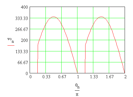
During the periods defined by 0
< wt < a, and p
< wt < p + a
, no SCR is in conduction and the output voltage is zero. The conduction
in the load is discontinuous.
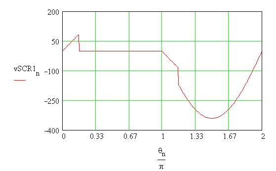
When no SCR is in conduction, it
is difficult to define the voltage across each SCR. The voltage source
is seen to be connected across the SCRs S1 and S3 are connected in series
with back-to-back. If it is assumed that the voltage gets divided between
the SCRs equally, we have that the voltage across the
SCR S1 is vs/2. Then
the voltage across the SCR S3 is -vs/2. Similarly the
voltage across the SCR S4 is vs/2 and the voltage across the SCR S2 is
- vs/2.
The voltage waveform of the output
and the waveform of the voltage across the SCR S1 are obtained and illustrated
below. The peak value of the supply voltage is defined as E.
E := 340 V a
: = p/6 rad
n:= 0..360 qn
:= (n.p)/180 vsn
:= E.sin(qn )
An expression is obtained in parts,
first for the positive half-cycle and then for the other half-cycle.
v1n := if(qn
< a , 0.0, E.sin(qn
))
von := if(n<180,v1n ,v1n-180
)
An expression for the voltage across
the SCR S1 is also obtained in parts.
v2n := if(qn
< a , vsn/2 , 0.0)
v3n := if(qn
< p , v2n , vsn/2 )
vSCR1n := if(qn
< (p+a) , v3n , vsn
)
The output voltage waveform
The voltage across the SCR S1
The variation of the output voltage
with firing angle can be obtained. At first, the maximum average voltage,
which occurs for 0o firing angle, is derived as a fraction of
the peak supply voltage.
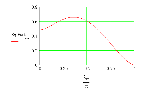
It is seen that the output voltage
is not pure d.c., even though a pure d.c. voltage is desirable as output.
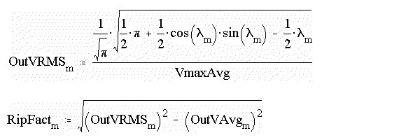
For a waveform such as the output of the rectifier, a factor of merit,
called the ripple factor is defined. The lower the ripple factor is the
better the output is. The ripple factor is defined as a function of extinction
angle, b and is called RF(b).
In some of the texts, the ripple
factor with the denominator as Vo,avg(a), but
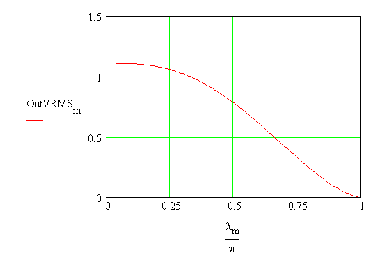
in this course, the denominator wil be set to be Vo,avg(max). The rms voltage
is obtained first and then the ripple factor can be obtained.
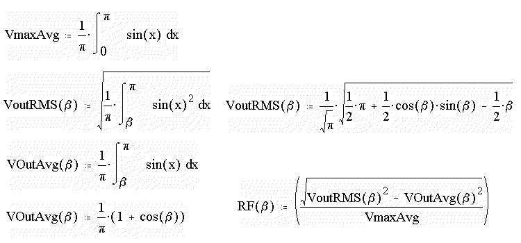
These functions can be evaluated
numerically as follows. The output voltage and the rms voltage are normalized
with respect to the maximum average voltage. The firing angle is called
lm.
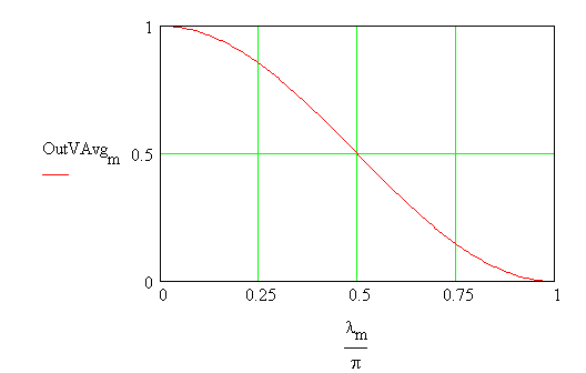
m:= 0..180 lm
:= (m.p)/180 OutVAvgm
:= [(1 + cos (lm
)]/[(p .VmaxAvg)]
The Plot of Average Output Voltage
as a function of firing angle
The plot of rms voltage and the
ripple factor are obtained as follows
The waveform of current drawn from
the supply is illustrated below. When the SCRs S1 and S4 conduct, the supply
current is just the load current. But when the SCRs S2 and S3 conduct,
the supply current is equal to the load current in magnitude, but of opposite
sign.
R := 10 W
iL1n := if(qn
< a , 0.0, (E/R).sin(qn
))
iL2n := if(qn
< p+a , 0.0, (E/R).sin(qn
))
iLinen := if(n<180,iL1n ,iL2n
)
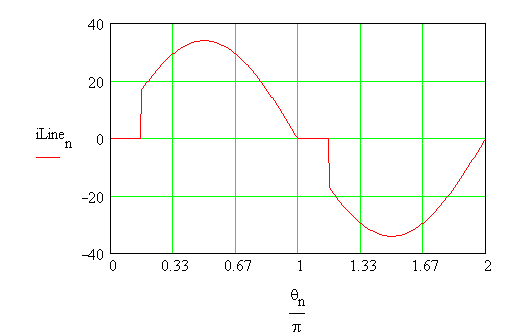
It is seen that the line current
is not purely sinusoidal. In such a case, a goodness factor called, the
THD (total harmonic distortion) is defined as shown. In the definition
for THD, Irms(a) represents the total rms current
and Irms,1(a) represents the rms
value of the fundamental component. The fundamental component is the line
frequency component. Here the calculations are carried out as function
of the firing angle, set to be lm.
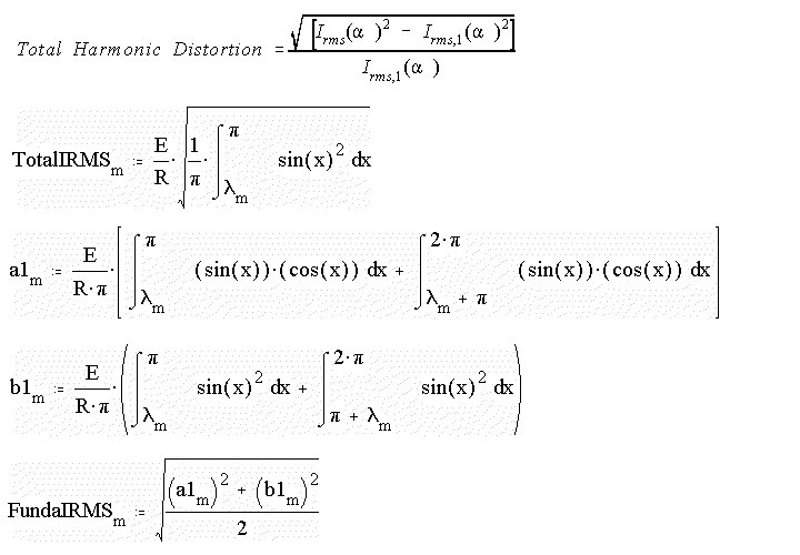
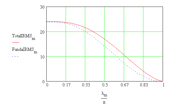
The variation of THD with the firing
angle is obtained as shown.

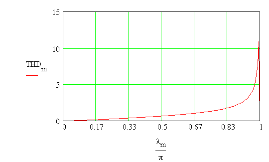
As seen, the THD increases as the firing angle
is retarded more and more.


