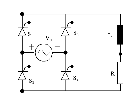

The operation of a fully-controlled
bridge rectifier circuit with RL load is explained in this program. This
bridge rectifier is fully-controlled, because all the devices used are
SCRs.
Let us assume that the circuit is switched on at wt = 0 and let the firing angle be a. Let the supply voltage vs(wt) = E sin (wt). When wt = a, the SCRs S1 and S4 get triggered and they start conducting since they are forward-biased. These two SCRs continue to conduct till wt = p. When wt = p radians, the supply voltage falls to zero, but the current through the load does not become zero because the current lags voltage in an RL load. When the current through the load is higher than the holding level for SCRs S1 and S4, they keep conducting by the inductor acting as a source. When the current through the inductor falls, the rate of change of current is negative and the voltage across the inductor is such that the terminal connected to the cathodes of SCRs S2 and S4 positive with respect to its other terminal and the inductor pumps energy back into the supply via the SCRs S1 and S4 and the load resistor. When p <wt < (p+a) radians, vs is negative and the output of the bridge rectifier is negative. If the current through the load has not decayed below the holding level for SCRs S1 and S4 till wt = (p+a) radians, the current through the load is continuous. At wt = (p+a) radians, the SCRs S2 and S3 are triggered and they take over conduction. Now the SCRs S1 and S4 are reverse-biased and they cease to conduct. The SCRs S2 and S3 are forward-biased when vs is negative and they get triggered and they continue to conduct either till wt = (2p+ a) radians when the SCRs S1 and S4 get triggered again in the next cycle or till the load current falls below the holding level of the SCRs used.
The time constant wL/R in radians
is set to be t. The peak value of E is not explicitly
stated. This means the voltages are normalized with respect to E. The currents
calculated are normalized with respect to E/R. Let the firing angle be
a radians.
t:=
1 radian Z:= sqrt(1 + t2)
a:= p/6 radian
deg := (a/p
).180
Let the circuit be switched on at
wt = 0. The periodic current response is obtained as follows. If the conduction
is continuous, i(a) = i(p+a).
For discontinuous conduction, i(a) = 0. Let
f = atan (t). Therefore
i(wt) = [E/Z]*sin (wt - f)
+ A*exp[- (wt - a)/t
].
For continuous conduction,
[E/Z]*sin(a-f) + A = [E/Z]*sin (p+a-f) + A*exp[- p/t ].
A = [(2E/Z)*sin (f-a)]/[1
- exp (-p/t) ].
For discontinuous conduction,
A = [E/Z] *sin (f
- a)
If a
< f, (firing angle < load angle) , the
conduction is continuous.
If a > f, (firing angle > load angle) , the conduction is discontinuous.
When a = f, (firing angle = load angle) , the conduction is about to become continuous and the value of A should satisfy both the equations. When a = f, A = 0 according to both equations. For this case, the current drawn from the source is sinusoidal and equals [E/Z]*sin (wt - f) !

b := atan (t)
n :=0..360
qn := (n.p)/180
vsn := E.sin(qn )
v1n := if(n<deg,-vsn ,vsn )
v2n := if[n<(180+deg),v1n ,-vsn ]

Cur2n :=
if (Cur1n> 0.0, Cur1n
,0.0)
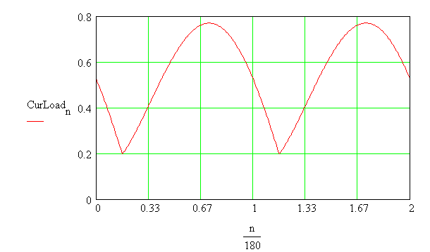
CurLoadn :=
if[n<(180+deg), Cur2n
,Cur2n-180 )
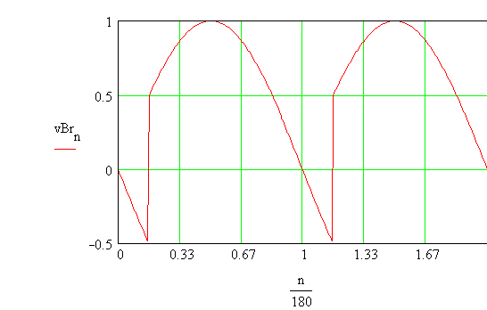
vBrn := if (CurLoadn
>0.0, v2n , 0.0 )
The plot of voltage of the bridge circuit

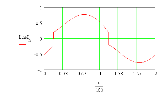
The line current is obtained as follows.
Cur3n := if(n<deg,
-CurLoadn ,CurLoadn )
LineIn := if[n<(180+deg),
Cur3n , -CurLoadn )
The waveform of load current

The plot of Line Current

The output voltage of the bridge contains ripples. The inductor can be assumed to have been provided to reduce the ripple in the load current. The line current contains harmonics. We can obtain expressions for the ripple factor of the output voltage of the bridge, the ripple factor of the load current and the THD in the line current. A program written in C presents the calculations and the plots.