PERFORMANCE CHARACTERISTICS

A symbolic representation of a separately-excited DC motor
is shown above. The resistance of the field winding is Rf
and its inductance is Lf, whereas the resistance of the armature
is Ra and its inductance is La. In the description
of the motor, the armature reaction effects are ignored. It is justifiable
since the motor used has either interpoles or compensating winding
to minimize the effects of armature reaction. The field current is
described by equation (1). If a steady voltage Vf is applied
to the field, the field current settles down to a constant value, as shown
in equation (2). When the field current is constant, the flux induced by
the field winding remains constant, and usually it is held at its rated
value f. If the voltage applied to the
armature is va, then the differential equation that is to be
applied to the armature circuit is shown in equation (3).
In steady-state, equation (4) applies.
The voltage, ea, is the back e.m.f. in volts. In a separately-excited
DC motor, the back e.m.f is proportional to the product of speed of motor
w rad/s and the field f Webers, as shown by
equation (5).
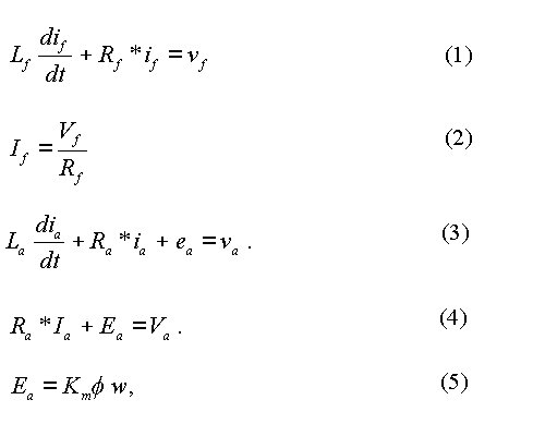
In equation (5), Km is a coefficient and its
value depends on the armature winding. If the armature current in
steady-state be Ia, then the power P that is supplied to the
armature is EaIa. This electric power
is converted to mechanical power by the armature of the DC motor. Let the
torque developed by the armature be Te, the unit
for torque being Nm (Newton-metre). Then power and torque can be
related as shown in equation (6). On canceling
the common term on both sides, the torque Te developed by the
armature is obtained as presented in equation (7).
If the instantaneous armature current is ia,
then equation (8) applies. Torque has been denoted by Te
in both equations.

The speed of the motor can be controlled by varying Va and holding Vf constant at its rated value. Then as the voltage applied to the armature is raised, the armature current increases first. As the armature current increases, the torque developed by motor increases and hence the speed of motor increases. The drop across the armature resistance tends to be small and hence the motor speed rises almost proportionately with the voltage applied to the armature. But there is a limit to the voltage that can be applied to the armature and that limit is the rated voltage of the armature voltage. The speed of the motor corresponding to the rated armature voltage and the rated field voltage is its rated speed. Thus the speed of a motor can be varied below its rated speed by controlling the armature voltage. It would be desirable that the motor should be able to develop as high as a torque as possible and hence the voltage rated applied to the field is held at its rated value. Applying higher than the rated voltage to either the field or the armature is not recommended. When the rated voltage is applied to the field, the flux would be near the saturation level in the poles. If a voltage higher than its rated voltage is applied to the field, the flux would saturate and there would not be any significant increase in the torque that the motor can deliver. On the other hand, this would only result in increased losses in the winding. Since the total heat which the DC motor can dissipate is fixed due to its surface area and cooling system, increased losses from the excitation system would mean that the other losses would have to reduce, implying that the armature current cannot be at its rated level and the maximum torque that the motor can deliver may reduce. Increasing the armature voltage above its rated value is not recommended because the insulation of the armature is designed for operation of the motor with the rated voltage applied to its armature. Moreover, the torque that the motor can deliver depends on the armature current and the field current. If the motor is operated continuously, the maximum armature current should not be higher than its rated value. When the armature current and the field voltage are at their rated level, the motor generates the rated torque. Hence the maximum torque the motor can deliver continuously over a long period of time is its rated torque when its speed is varied from a low value to its rated speed. Over this period, 0 < w < wr, where wr is its rated speed, the power output is given by:
![]()
The maximum torque which the motor can deliver continuously
is called Te,max cont. What is being referred to here
is the maximum torque the motor can deliver, and not the actual torque
the motor delivers. The actual torque the motor delivers depends
on the mechanical load connected to its shaft. If the speed of the
motor is to be increased beyond its rated value, the voltage applied to
the armature can be held at its rated value and the field can be weakened
by reducing the voltage applied to it. When the speed of the motor
is in this manner, the maximum power that can be supplied to the armature
is fixed, since both the voltage applied to the armature and the armature
current cannot exceed the rated level over a long period. That means
the maximum torque the motor can develop above the rated speed is:
The plots of Te,max cont and the maximum
power Pa,max can be plotted as a function of rotor speed as
shown below. The rated values
of speed, torque and power to the armature have been set equal to unity.
A separately-excited dc motor can be controlled, either by varying the voltage applied to the field winding or by varying the voltage applied to the armature. This page describes how the motor can be controlled by varying the armature voltage and it is assumed that the field is excited by a constant voltage, equaling the rated voltage of the field winding. It means that the discussion to follow assumes that the field current remains steady at its rated value.
The block diagram of a dc drive is shown above. It does not show all details. The DC motor has not been represented in the form of a block diagram and the details of the load the motor drives have also not been shown. The block diagram functions as follows.
For the system described here, the output of the system is the speed of the motor. Hence when this system is to be controlled in closed-loop, the parameter that is to be set is what that speed should be. It is denoted to be Wref. In order to control the speed in closed-loop, we need a feedback signal too. It can be obtained in several ways. A digital tacho or an analogue tachogenerator can be used. It is assumed that an analogue tachogenerator is used here. It is coupled to the motor shaft and its output voltage varies linearly with its speed. Let the speed feedback signal be Wf. This signal can be compared with the speed reference signal and the error can be processed by a controller. The controller can be of one of several types. It can be an integral controller, or a PI controller and PDF (pseudo-derivative feedback) controller or a PID controller or a rule-based fuzzy logic controller. Here both the controllers used are PI (proportional plus integral) controllers. A PI controller can lead to fast response and zero-error for a step input.
The PI controller for speed has as its input the error between the two signals, Wref and Wf. If the speed feedback signal Wf is lower than the reference signal Wref , it means that the DC motor speed is running below the set speed and it needs to be accelerated. In order to accelerate the motor, it should develop greater torque. To develop greater torque, its armature current has to increase. Hence the output of speed controller is set to function as the reference signal for armature current. It will be a voltage corresponding to armature current with an appropriate coefficient linking the two quantities. When Wf < Wref , the difference causes the output of speed controller to increase. Since the output of speed-controller is set to function as the armature current reference signal, an increase in the value of speed-controller output would in turn lead to an increase in the armature current.
The rectifier circuit is made up of SCRs and the SCRs have a current rating. Hence it is necessary to ensure that the current through the SCRs remains within a safe level. Hence the output of speed controller is limited at both ends. Its maximum value corresponds to the safe level for SCRs. It is not normally the rated current of the motor and it is usually set at a value ranging from 1.5 times to 2 times the rated armature current. The reason is that the motor may have to develop more than the rated torque under transient conditions to achieve fast response. In order to ensure that the motor armature current remains within its rated value, another supervisory loop may be used. Another option is to use a circuit-breaker. The instantaneous trip action in the circuit breaker can be due to magnetic effect and the overload trip can be due to thermal action. A bi-metallic strip within the circuit-breaker expands due to temperature and would trip circuit-breaker. The lower limit on the output of speed-controller would correspond to zero current in the armature, since the motor current in this scheme cannot be in the reverse direction.
The current controller has two inputs, the reference current signal which is the output of the speed controller and a feedback signal proportional to the armature current. The feedback signal can be obtained in several ways. A current transformer can be introduced in the path of ac current from the ac supply. Another option would be to use a DC current transducer that makes use of a Hall-effect sensor or isolated opamp. The transducer used produces a voltage proportional to the current in the armature. The difference between these two signals is processed by another PI controller and its output is also limited to correspond to 0o and 180o firing angle. The output of current controller may vary between 0 V and 10 V, with 0 V corresponding to 180o firing angle and 10 V corresponding 0o firing angle. If the firing angle be a and the output of current controller VC, then
![]()
As the output voltage of current controller increases
due to the difference between the reference signal and the feedback signal
corresponding to armature current, the firing angle is advanced towards
0o and the average output voltage of the bridge rectifier increases.
This in turn leads to increased torque generation and the motor accelerates.
If the speed reference is brought down suddenly, the current in the motor cannot be reversed and hence the motor slows down due to friction and the load. This process can be slow.
The question that can be raised is whether we need the current loop. The answer is that it improves the performance. If there is a change in the supply voltage even by a small amount, the output of the bridge circuit tends to a fall a bit for the same firing angle. The reduction in output voltage causes a large change in the armature current, with the speed remaining more or less. The current loop comes into action, correcting the firing angle to the required value. The time constant of the armature, due to its inductance and resistance, tends to be of the order of a few tens of ms and the mechanical time constant, due to the moment of inertia of motor and load and the friction, is of the order of a few tenths of a second. If a current controller is not used, the speed would have to change before the speed controller can come into action. Since the mechanical time constant is about at least 10 times greater, there would be a significant change in speed if there be no current controller.
Normally a filter may be necessary in the feedback circuit
for speed. The tacho signal usually contains a small ripple superimposed
on its dc content. The frequency of the ripple is usually dependent
on the speed and the lower the speed is the lower is the frequency of this
ripple. Hence the time constant of the filter may have to be set
to correspond to the lowest speed at which the motor would be required
to run. Usually the motor speed does not have to vary over a range
larger than 0.1 p.u to 1 p.u. Since the power output varies proportionately
with the speed, there is usually no justification to run the motor at an
extremely low speed. The next section describes how the simulation
is carried out. The routines are explained with the help of
pseudo-code that can be understood by a reader with some knowledge of one
of the programming languages such as C, PASCAL, BASIC, Fortran or Matlab.
CLOSED-LOOP CONTROL
This section explains how the simulation can be carried
out.
Initialize_Routine:
Set and
get Parameters
Initialize
controller Outputs
Go to Calculation_Routine
Calculation_Routine
Execute
One_Cycle_Routine
Plot the
results
One_Cycle_Routine
Set angle
to zero.
For (angle
= 0; angle <360o; angle +stepsize)
{
Set the SCR pair based on firing angle and angle.
Go to Next_Values
}
Next_Values
Calculate
the increments in
armature current
motor speed
tacho filter output
speed controller output
current controller output
Add the
increments
Compute
the firing angle
The pseudo-routine presents only the main steps.
Before selecting the type of response, set the value of the selected parameter. When you select a parameter, the textfield shows the default value set inside the program. Change the parameter value if you want to and then you must click on the SET VALUE button for the change to take effect. You can go from one type of response to another after the present calculations are carried out. When you have selected a new type of response, you must click on Click to Start. If you click on Reset button, initializing routine is carried out and the motor speed is set to zero, and the other values are also reset. The program has been written assuming that the frequency of operation is 50 Hz. If the frequency is different, the parameter values should be scaled suitably.
Next page describes how a three-phase fully-controlled bridge rectifier circuit operates.