Let the three-phase voltages be defined as shown below.
![]()
It can be seen that the R-phase voltage is the
highest of the three-phase voltages when q is
in the range from 30o to 150o. It can also be seen
that Y-phase voltage is the highest of the three-phase voltages when q
is in the range from 150o to 270o and that B-phase
voltage is the highest of the three-phase voltages when q
is in the range from 270o to 390o or 30o
in the next cycle. We also find that R-phase voltage
is the lowest of the three-phase voltages when q
is in the range from 210o to 330o. It can also be
seen that Y-phase voltage is the lowest of the three-phase voltages when
q is in the range from 330o to 450o
or 90o in the next cycle, and that B-phase
voltage is the lowest when q is in the range
from 90o to 210o. If diodes are used, diode
D1 in place of S1 would conduct from 30o
to 150o, diode D3 would conduct from 150o
to 270o and diode D5 from 270o
to 390o or 30o in the next cycle.
In the same way, diode D4 would conduct from 210o
to 330o, diode D6 from
330o to 450o or 90o in
the next cycle, and diode D2 would conduct from 90o
to 210o. The positive rail of output voltage of the bridge
is connected to the topmost segments of the envelope of three-phase voltages
and the negative rail of the output voltage to the lowest segments of the
envelope.
At any instant barring the change-over periods when current flow gets transferred from diode to another, only one of the following pairs conducts at any time.
| Period, range of q | Diode Pair in conduction |
| 30o to 90o | D1 and D6 |
| 90o to 150o | D1 and D2 |
| 150o to 210o | D2 and D3 |
| 210o to 270o | D3 and D4 |
| 270o to 330o | D4 and D5 |
| 330o to 360o and 0o to 30o | D5 and D6 |
| Period, range of q | SCR Pair in conduction |
| a + 30o to a + 90o | S1 and S6 |
| a + 90o to a + 150o | S1 and S2 |
| a + 150o to a + 210o | S2 and S3 |
| a + 210o to a + 270o | S3 and S4 |
| a + 270o to a + 330o | S4 and S5 |
| a + 330o to a + 360o and a + 0o to a + 30o | S5 and S6 |
To vary the output voltage, it is necessary to vary the firing angle. In order to vary the firing angle, one commonly used technique is to establish a synchronizing signal for each SCR. It has been seen that zero degree firing angle occurs 30o degrees after the zero-crossing of the respective phase voltage. If the synchronizing signal is to be a sinusoidal signal, it should lag the respective phase by 30o and then the circuitry needed to generate a firing signal can be similar to that described for single-phase. Instead of a single such circuit for a single phase rectifier, we would need three such circuits.
When the 3-phase source supply connected to the rectifier
is star-connected, the line voltages and the phase voltages have a 30o
phase angle difference between them, as shown below.
The line voltage can also be obtained as:
This line voltage lags the R-phase voltage by30o and has an amplitude which is 1.732 times the amplitude of the phase voltage. The synchronizing signal for SCR S1 can be obtained based on vRB line voltage. The synchronizing signals for the other SCRs can be obtained in a similar manner.
To get the synchronizing signals, three control transformers can be used, with the primaries connected in delta and the secondaries in star, as shown below.
For S1, voltage vS1 is used as
the synchronizing signal. Voltage vS2 is used as the synchronizing
signal for SCR S2 and so on. The waveforms presented by the
synchronizing signals are as shown below. The waveforms do not show
the effect of turns ratio, since any instantaneous value has been normalized
with respect to its peak value. For example, let the primary phase
voltage be 240 V and then its peak value is 339.4 V. The primary
voltage is normalized with respect to 339. V. If the peak voltage
of each half of secondary is 10 V, the secondary voltage are normalized
with respect to 10 V.
Analysis of this three-phase controlled rectifier is in many ways similar to the analysis of single-phase bridge rectifier circuit. We are interested in output voltage and the source current. The average output voltage, the rms output voltage, the ripple content in output voltage, the total rms line current, the fundamental rms current, THD in line current, the displacement power factor and the apparent power factor are to be determined. In this section, the analysis is carried out assuming that the load current is a steady dc value.
AVERAGE OUTPUT VOLTAGE
Before getting an expression for the output voltage, it is preferable to find out how the output voltage waveform varies as the firing angle is varied. In one cycle of source voltage, six pairs conduct, each pair for 60o. This means that the period for output waveform is one-sixth of the period of line voltage. The output waveform repeats itself six times in one cycle of input voltage. The waveform of output voltage can be determined by considering one pair. It is seen that when vR(q) = E* Sin (q), SCR S1 and S6 conduct when q varies from 30o + a to 90o + a , where a is the firing angle. Then
The waveform of output can be plotted for different firing angles. The applet below takes in the firing angle as an input and plots the output. The peak line-to-line voltage is marked as 'U' and the applet starts with the instant an SCR is fired and displays the output waveform for one input cycle period.
The average output voltage of the bridge circuit is calculated
as follows, with a change in variable, where q
= a + 60o.
In the expression above, U is the peak line-to-line voltage, whereas E is the amplitude of phase voltage of 3-phase supply.
RMS OUTPUT VOLTAGE
The rms output voltage is calculated as follows:
The ripple factor of the output voltage is then:
The applet below displays the average output voltage, the rms output voltage and the ripple factor for the case of continuous conduction through the load.
It is seen that the average output voltage is negative when firing angle exceeds 90o. It means that power flow is from the dc side to the ac source. When the firing angle is kept in the region 0o < a < 90o, this circuit is said to be operating in the rectifier region. When the firing angle is kept in the region 90o < a < 180o, this circuit is said to be operating in the inverter region. When the circuit operates in the rectifier region, the net power flow is from the ac source to the dc link. In the inverter region, the net power flow is in the reverse direction. To operate in the inverter region, it is necessary to have a dc source present in the dc link which can provide the power that is fed back to the ac source.
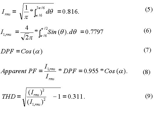
RMS LINE CURRENT
The rms line current is relatively easy to find out if the dc current is ripple-free and steady. The load current is ripple-free if the inductance in the dc link is relatively large. To maintain load current at any firing angle, it is necessary that the dc link should contain a voltage source. Given that the resistance of the load circuit is zero, the voltage source should equal the average output voltage of the bridge circuit. The waveforms shown below are based on the assumption that these conditions are met. It has been shown that if vR(q) = E*Sin (q), SCR S1 conducts when q varies from a + 30o to a + 90o and that SCR S4 conducts when q varies from a + 210o to a + 270o. If the amplitude of dc load current is assigned to be unity, the line current waveform is then a rectangular pulse, remaining at + 1 from a + 30o to a + 150o, at - 1 from a + 210o to a + 330o, and zero elsewhere. The amplitude of the fundamental in line current is then 3.464/p ( which evaluates to nearly 0.78) and the amplitude of other odd harmonics is 3.464/np, where n is the odd harmonic number. When the dc load current is steady and has a magnitude of unity, the rms line current is obtained as shown in equation (5). The rms value of the fundamental is obtained as shown in equation (6). Equation (6) is based on how trigonometric Fourier coefficients are defined for waveforms with quarter-wave symmetry. When the line current is a rectangular and symmetric, the phase current is the same as the line current and the fundamental component of the phase current lags the phase voltage by an angle equal to the firing angle. Hence the displacement power factor is expressed as shown by equation (7). Since the line current is not sinusoidal, the apparent power factor, usually referred to just as the power factor in most of the texts, is less than DPF and is represented by equation (8). Since the line current is not sinusoidal, the distortion component in the line current has to be computed. This component, called the THD( Total Harmonic Distortion ), is calculated as shown in equation (9).
The applet displayed below simulates the circuit in the
form of animation. The only parameter to be set is the firing angle
and the program can be run for a single-cycle or stepped through.
You can click on Pause button to pause and view the display.
The next page describes the operation of this rectifier circuit with just a resistive load and a dc source in the dc link.