Since the load current tends to be discontinuous, two expressions for the average output voltage can be derived, one for the continuous mode and the other for the discontinuous mode. In the continuous mode, the average output voltage is as shown in equation (1). The conduction becomes discontinuous when the firing angle exceeds 60o and remains less than 120o. Then the average voltage is obtained as shown in equation (2).

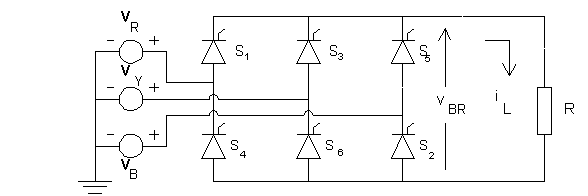
In equations (1) and (2), the amplitude of phase voltage is designated as E and the amplitude of line voltage is designaed as U.
The rms voltage is computed as follows. When a
< 60o, the conduction is continuous and the expression for
the rms voltage is presented in equation (3), whereas equation (4) expresses
the rms voltage obtained when firing angle a
> 60o.

The ripple factor can be found out as defined in the
previous page.
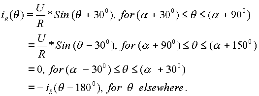
The line/phase current can be defined as follows. Let R-phase voltage be defined to be
vR(q) = E*Sin (q).
Then the R-phase current iR(q) is defined as follows, when the conduction is continuous.
When the conduction is discontinuous,
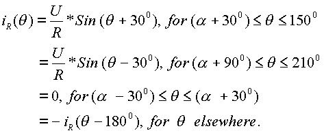
From this definition of phase current, the rms line current, the rms of the fundamental in line current and its THD can be found out.
The applet below displays the average output voltage, the rms output voltage, its ripple factor, the rms line current, the fundamental rms content in line current and its THD as a function of firing angle. The peak average output voltage, (3U/p), is taken to be unity and (3U/pR) is set equal to unity, where R is the load resistor.
The applet shown below displays the source voltage, the
output voltage, the current in R-phase and the voltage across SCR S1.
In addition, the relevant statistical details are also displayed.
To run the applet, key-in the firing angle and then click on Start
Button.
The Pspice program for simulation of this three-phase rectifier circuit is presented below. The model used for the SCRs is the same as defined for the single-phase fully-controlled bridge rectifier. The three-phase brdige rectifier contains six SCRs and it is necessary to define six pulse sources, one for each SCR. The pulse sources have been defined for a firing angle of 30o and the frequency of the three-phase source is 50 Hz. At any time two SCRs need to conduct, one from the top half and another bottom half and hence only if one SCR is triggered at a time, conduction may never get established. To overcome this problem, two SCRs are triggered at the same time. For example, when SCR S2 is to be triggered, SCR S1 is also triggered. In the same way, when SCR S3 is to be triggered, SCR S2 is also triggered and so on. In order to effect this in program, one voltage-controlled voltage source is defined for each SCR. The dependent source defined for SCR S1 is dependent on two sources, the pulse source that defines when SCR S1 is to be triggered and the pulse source that defines when SCR S2 is to be triggered.
* Three-phase Full-wave Fully-Controlled Bridge Rectifier
VA 1 0 SIN(0 340V 50Hz)
VB 2 0 SIN(0 340V 50Hz 0 0 -120)
VC 3 0 SIN(0 340V 50Hz 0 0 -240)
XT1 1 4 11 4 SCR
XT3 2 4 13 4 SCR
XT5 3 4 15 4 SCR
XT4 5 1 14 1 SCR
XT6 5 2 16 2 SCR
XT2 5 3 12 3 SCR
RP 4 0 100K
RN 5 0 100K
R1 4 5 10

VP1 21 0 PULSE(0 10 3333.3U 1N 1N 100U 20M)
VP2 22 0 PULSE(0 10 6666.7U 1N 1N 100U 20M)
VP3 23 0 PULSE(0 10 10M 1N 1N 100U 20M)
VP4 24 0 PULSE(0 10 13333.3U 1N 1N 100U 20M)
VP5 25 0 PULSE(0 10 16666.7U 1N 1N 100U 20M)
VP6 26 0 PULSE(0 10 0M 1N 1N 100U 20M)
RP1 21 0 100K
RP2 22 0 100K
RP3 23 0 100K
RP4 24 0 100K
RP5 25 0 100K
RP6 26 0 100K
EP1 11 4 poly(2) (21,0) (22,0) 0 1 1
EP2 12 3 poly(2) (22,0) (23,0) 0 1 1
EP3 13 4 poly(2) (23,0) (24,0) 0 1 1
EP4 14 1 poly(2) (24,0) (25,0) 0 1 1
EP5 15 4 poly(2) (25,0) (26,0) 0 1 1
EP6 16 2 poly(2) (26,0) (21,0) 0 1 1


* Subcircuit for SCR
.SUBCKT SCR 101 102 103 102
S1 101 105 106 102 SMOD
RG 103 104 50
VX 104 102 DC 0
VY 105 107 DC 0
DT 107 102 DMOD
RT 106 102 1
CT 106 102 10U
F1 102 106 POLY(2) VX VY 0 50 11
.MODEL SMOD VSWITCH(RON=0.0105 ROFF=10E+5 VON=0.5 VOFF=0)
.MODEL DMOD D((IS=2.2E-15 BV=1200 TT=0 CJO=0)
.ENDS SCR


.TRAN 10US 60.0MS 0.0MS 10US
.PROBE
.OPTIONS(ABSTOL=1N RELTOL=.01 VNTOL=1MV)
.END
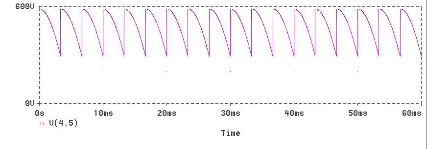
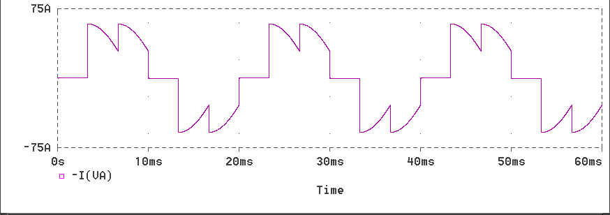
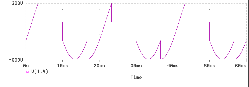
The responses obtained for a load resistance of 10W are presented below.
The Output Voltage Waveform
This page has described the operation of the three-phase
fully-controlled bridge rectifier with a resistive load. The next
page describes how this rectifier functions when the load contains an inductor
also.