This page describes the operation of the three-phase semi-controlled
rectifier. When a semi-controlled rectifier is used, the output of the
bridge is controlled when it remains positive. If it tends to become negative,
the output is clamped to zero volt through the free-wheeling action of
the diodes.

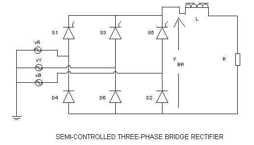
The circuit of the semi-controlled bridge rectifier is shown in Fig. 1, and this circuit contains three-SCRs and three diodes. It is possible to configure the circuit in two more ways. For example, the top-half can contain the diodes and the bottom half the SCRs. Alternatively, six SCRs can be used as in the case of the fully-controlled bridge rectifier and an additional diode can be connected from the negative rail to the positive rail of the bridge, with the anode connected to the negative rail and the cathode to the positive rail. The operation of this circuit is different from that of the circuit displayed above.
The operation of the semi-controlled rectifier circuit displayed in Fig. 1 is now explained. The waveform of the bridge output voltage for a firing angle of 30o is shown in Fig. 2. .It can be seen that the trace of the positive rail of output voltage is that of a controlled rectifier, since only the top-half of the bridge is controlled. The trace of the bottom rail is that of an uncontrolled bridge rectifier, since the bottom half contains only diodes.

Fig. 2
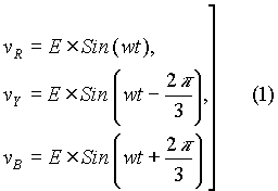
Let the 3-phase supply be defined as shown in equation (1).

Given that the firing angle is 30o, SCR S1 is triggered when wt = 60o . The conduction range of the SCRs in the top half can be is now expressed in equation (2).


As long as the firing angle a remains less than 60o, the expression for output voltage over one output cycle can be expressed as follows.
Substituting for vR, vY, and vB from equation (1), we get that

When the firing angle a is higher than 60o, the expression for output voltage over one output cycle can be expressed as follows, if conduction through the load is continuous.

Substituting for vR, and vB from equation (1), we get that

Depending on the firing angle, the bridge output repeats itself every 120o. The applet shown below plots the output voltage, given the firing angle. It is assumed that conduction through the load impedance is continuous.

If the firing angle a is less than 60o, when SCR S1 is triggered, SCR S1 and diode D6 conduct during the period (a + 30o) £ wt < 90o. Figure 3 shows the path of conduction that would exist during this period. The pairs that conduct vary depending on the firing angle. Table 1 show the pairs that would conduct when the firing angle a is less than 60o, whereas Table 2 shows the pairs that would conduct when the firing angle a is greater than 60o.
The aims of anlysis are:
| S1 – D6 | (a + 30o) £ wt < 90o |
| S1 – D2 | 90o £ wt < (a + 150o) |
| S3 – D2 | (a + 150o) £ wt < 210o |
| S3 – D4 | 210o £ wt < (a + 270o) |
| S5 – D4 | (a + 270o) £ wt < 330o |
| S5 – D6 | 330o £ wt < (a + 390o) |
| S1 – D2 | (a + 30o) £ wt < 210o |
| S1 – D4 | 210o £ wt < (a + 150o) |
| S3 – D4 | (a + 150o) £ wt < 330o |
| S3 – D6 | 330o £ wt < (a + 390o) |
| S5 – D6 | (a + 270o) £ wt < 450o |
| S5 – D2 | 90o £ wt < (a + 30o) |
When the conduction through the load is continuous, the average bridge output voltage is obtained as shown below.
Given that the firing angle is less than 60o,

If the firing angle is greater than 60o and the conduction is continuous,

The maximum output voltage occurs when a = 0o and let it be Vdm:

From equation (7) and (9), we obtain that

RMS Output Voltage
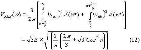
The expression for the rms output voltage is found separately for the two cases. The assumption here is that the conduction is continuous. When the firing angle is greater than 60o,

When the firing angle is less than 60o,

Ripple Factor of the Bridge Output Voltage
The ripple factor, RF(a), of the bridge output voltage can be computed as follows:

Since both VRMS(a) and VDC(a) are known, the ripple factor can be computed.
Instantaneous Load Current
An expression for the instantaneous load current as a function of firing angle can be obtained through a somewhat tedious process.
When the firing angle is less than 60o, the instantaneous bridge output voltage expressed by equation (4) is reproduced below.

The above expression can be written with the origin shifted to the instant of triggering an SCR. Then

Let the load angle be:

The expression for load current during 0o £ q £ (60o – a) can be expressed to be:

In the expression, A1 is a constant to be evaluated. Then


The expression for load current during (60o – a) £ q £ 120o can be expressed to be:

In equation (20), A2 is a constant to be evaluated. Then

Another expression for the load current can be obtained when the output cycle ends.

When the load current is periodic, then
![]()
From equations (18), (19), (21) , (22) and (23), we can determine A1 and A2. From equations (19) and (21), we get that

On simplifying the above expression, we get that

From equations (18), (22) and (23), we get that

On simplifying the above expression, we get that

Substituting for A2 from equation (26),

Then A2 can be determined from equation (25).
Since both A1 and A2 are known, the expression for load current has been obtained for the case when the firing angle is less than 60o.
When the firing angle is greater than 60o,

Then the load current can be expressed to be:

In the above equation, A3 and A4 have to be determined. The conditions we have are:

On solving for A3, we obtain that

Now an expression for the load current is known for any firing angle.
Instantaneous Load Current
An expression for the instantaneous line current as a function of firing angle can be obtained from the expression for the load current. Here an expression for current through R-phase over an input cycle is obtained with the origin coinciding with the triggering of SCR S1. When SCR S1 is in conduction, the line current is equal to the load current Then
When the firing angle is less than 60o,

When the firing angle is greater than 60o,

RMS Line Current
Since the line current iL(q) is known over one input cycle, the rms line current can be obtained.

RMS Value of the Fundamental of Line Current
By performing Fouries series analysis of the line current, the rms value of the fundamental can be obtained. From the rms line current and the rms value of the fundamental of line current, THD can be computed.
The applet that folows requires two inputs, the firing
angle in degrees and the load reactance to resistance ratio, wL/R. Select
the response and then click on the RUN button.
This page has described the simulation of a semi-controlled three-phase bridge rectifier. Some more topics on controlled rectifier are covered in later pages.